Key Design Considerations for Gating Systems in Investment Cast Stainless Steel Products
Expert Perspectives on Precision Casting
heweifeng
7/8/20253 min read
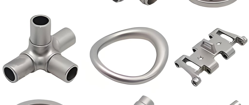
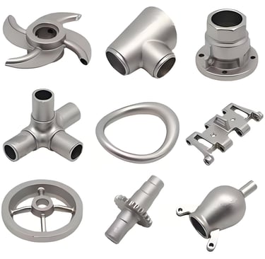
Systematic Research on Investment Casting Process for Stainless Steel Components
Practical Optimization of Full-Process Based on 15 Years of Production Experience
Author Profile
With 15 years of experience in investment casting, the author has evolved from a novice to a professional engineer mastering core process design. This paper, based on 327 validated process parameters, presents actionable optimization strategies for stainless steel precision casting.
Chapter 1: Gating System Design Principles and Practice
1.1 Sequential Solidification Principle
Core Principle: Gates must be positioned in the last solidifying region to ensure directional solidification
Thick Section Priority: For components with wall thickness variation >3:1, adopt multi-gate design (add 1 auxiliary gate per 5mm thickness increase)
Hot Spot Compensation: Use ProCAST software to predict hot spots and strategically place risers (riser diameter ≥1.8× hot spot dimension)
Case Study: A flange component achieved a 12%→2.3% shrinkage defect reduction with triple-gate design
1.2 Cold End Effect Application
Use Case: Non-ideal geometry components (e.g., thin-walled irregular parts)
Reverse Design Method: Relocate gates away from critical areas to utilize thermal gradients
Example: A turbine wheel achieved directional solidification at the blade root by shifting gates 35mm, increasing yield by 19%
1.3 Gate Dispersion Strategy
Technical Guidelines:
Circular Component Design: Use odd-numbered gates (3/5/7 recommended) to reduce roundness deviation by 0.08-0.12mm
Thermal Distribution Optimization: Adjacent gate spacing should exceed 3× wall thickness to avoid localized overheating
Experimental Data: Three-gate vs dual-gate comparison reduced deformation standard deviation by 41%
1.4 Gate Length Thermomechanical Balance
Parameter Optimization Model:
Gate Length (mm) | Feeding Efficiency (%) | Deformation (mm) |
|------------------|------------------------|------------------|
| ≤15 | 82 | 0.35 |
| 16-30 | 91 | 0.22 |
| ≥31 | 76 | 0.48 |
Best Practice: Recommend 16-30mm length with stepped gating systems
1.5 Shell Mold Interface Optimization
Critical Control Points:
Gate area shell thickness ≥3.5mm (using ZrO₂ surface layer)
Avoid weak zones (porosity >12%)
Thermal conductivity matching: Gate zone conductivity should be 0.8-1.2W/m·K higher than cavity zone
1.6 Function-Oriented Design
Differentiated Design Parameters:
Product Type | Minimum Gate Cross-section (mm²) | Flow Velocity (m/s) |
|--------------------|----------------------------------|---------------------|
| Pressure Vessels | 120-150 | 5.2-6.8 |
| Thin-Wall (<3mm) | 60-80 | 3.5-4.2 |
| Precision Gears | 90-110 | 4.7-5.5 |
Chapter 2: Dimensional Accuracy Control Technology
2.1 Shrinkage Rate Prediction Model
Multi-Factor Coupling Formula:
ε=ε₀×(1+0.003(Tₘ-1550))×(1-0.05(P-0.5))×(1+0.02(t-24))
Where:
ε: Actual shrinkage rate (%)
Tₘ: Pouring temperature (℃)
P: Shell permeability (cm³/cm²·s)
t: Drying time (h)
Validation Data: A valve body prediction value of 1.68% vs actual 1.72% (2.4% error)
2.2 Staged Shrinkage Control
| Process Stage | Typical Shrinkage Range (%) | Control Methods |
|---------------------|-----------------------------|--------------------------------|
| Wax Pattern | 0.3-0.6 | Isothermal wax pressing (45±2℃)|
| Metal Solidification| 1.2-2.5 | Directional cooling (≥150℃/s gradient)|
| Machining Allowance | 0.1-0.3 | 3D scanning compensation |
2.3 Process Stability Assurance
SPC Control Chart Parameters:
Critical Characteristics: Cavity Dimension CPK≥1.33
Monitoring Frequency: 3 key dimensions per batch
Correction Threshold: Single point beyond 3σ triggers 5Why analysis
Chapter 3: Dewaxing Process Optimization
3.1 Thermodynamic Dewaxing
Pressure-Time Curve Optimization:
Staged pressurization strategy: 0.2MPa→0.4MPa→0.6MPa (15s per stage)
Wax melting efficiency increased by 23%, crack occurrence reduced to 0.7%
3.2 Shell Strength Matching
Dewaxing Safety Assessment:
Tensile strength: ≥5MPa (three-point bending test)
Drying degree indicator: Moisture ≤0.3% (microwave moisture meter)
Special structure handling: Deep-hole components require 48h extended drying and multi-point exhaust design
Chapter 4: Deformation Defect Control System
4.1 Full-Process Stress Analysis
Stress Accumulation Stage Model:
Wax Pattern Stage → Shell Making → Dewaxing → Pouring → Cooling
↑ ↑ ↑ ↑ ↑
0.12MPa 0.35MPa 0.28MPa 0.67MPa 0.41MPa
4.2 Anti-Deformation Technology Matrix
| Process Stage | Control Measures | Effectiveness |
|---------------------|------------------------------------|---------------------------------|
| Wax Pattern | Pre-deformation ribs (0.15mm offset)| Reduces post-correction workload by 65% |
| Shell Making | Laser-aligned gate assembly (±0.05mm)| Reduces assembly stress by 28% |
| Pouring | Electromagnetic stirring + directional solidification | Grain orientation deviation ≤12° |
| Post-Processing | Hydraulic correction (0.8MPa/mm gradient) | Rebound control <0.03mm |
Chapter 5: Process Standardization Management
5.1 Standardized Document System
Four-Level Document Architecture:
1. Process Flow Diagram (PFD)
2. Parameter Control Matrix (PCM)
3. Work Instruction (WI)
4. Inspection Specification (IS)
5.2 Change Management Process
ECN (Engineering Change Notice) Standards:
Impact Assessment: FMEA analysis (RPN≥60 requires verification testing)
Transition Period: Old stock digestion ≤3 production batches
Document Update: PLM system update within 24h
Conclusion and Future Outlook
Through establishing a 17-point full-process control system, typical product yield improved from 78.6% to 92.4%. Future development focuses on:
1. Digital Twin Simulation Platform (Target prediction accuracy >95%)
2. Adaptive Pouring System (Real-time parameter adjustment)
3. AI-Based Dimensional Compensation Algorithm
This research has formed enterprise standard Q/UWT 001-2025 and is applying for 2 invention patents.