Long hole narrow groove casting melt mold casting process method
Precision long-hole narrow-groove casting via optimized melt mold process ensures high accuracy, reduced defects, and superior surface finish for complex metal components
heweifeng
7/22/202512 min read
Investment casting shell is a repetition of the process of “coating - sand - drying”. But for the castings with long holes, narrow grooves such a structure, due to the long holes, narrow grooves inside is not easy to paint, sprinkle sand, when the through-hole hole depth and diameter ratio H/d>5, narrow grooves groove depth or length to width ratio is greater than a certain ratio is difficult to cast, often using mechanical processing methods to achieve. For long holes with a slightly larger diameter, although the shell can be made, but has been filled with slurry, sand, increasing the chance of shrinkage, shrinkage defects. In this paper, we discuss several methods of investment casting of such castings.
1.1 immersion slurry method
in the shell of two or three layers, the shell will be immersed in the slurry, so that the slurry filled with long holes or narrow grooves in the shell of the remaining space, to be one of the slurry dry, and then the next layer of shell production. The purpose is to increase the strength of the type shell in the hole and prevent the phenomenon of runout.
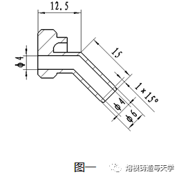
1.2 Example: The structure of Joint A is shown in Fig. 1.
There is a Φ4×25 elongated hole, which is intersected at 135°, with a thickness of 1mm in the hole wall and 0.7mm in the head, and the piece is small and light, with a mass of 9.5g. Information: when the hole diameter is Φ3~Φ5, the maximum depth of the hole can be casted out to be 5~10mm, i.e., the ratio of the depth of the hole to the hole diameter is The ratio of hole depth to hole diameter is 1.4~3.3, while the ratio of hole depth to hole diameter of this piece is 6.25, so it can be seen that Φ4 hole shell making is the difficulty of this piece.
The first and second layer shells are made of zirconium material, the first layer shell is about 0.5mm thick, the second layer shell is about 0.75mm thick, after making two layers of shells, the Φ4 orifice is only about Φ1.5mm, when making the shells of the third layer, the sand is spread with 30-60 mesh of molybdenum sand, the particle size of which is 0.2-0.6mm, and the long holes are intersected by 135°, so the normal sand spreading in the holes with the paint is not realized. But two layers of zirconium material shell strength is small, can not resist 1600 ℃ above the high temperature steel flushing, will produce the phenomenon of running fire to form scrap. In the second layer of shell production after the use of “dip slurry method” to increase the strength of the shell to meet the requirements of mass production.
1.3 Key points of the process
①Dipping slurry: silica sol+molybdenum powder (200 mesh), viscosity 20±2S. large viscosity, dip slurry flow is not good, not easy to fill; viscosity is small, dip slurry seems to be full, but after drying due to the evaporation of water will leave more voids, affecting the strength.
② Blow out the floating sand in the long hole before dipping the slurry.
③The type shell must be dry after dipping pulp to ensure the strength. Joint A three layers of dip pulp after drying time of 24 hours, drying conditions: temperature 24 ± 2 ℃, humidity 40 ~ 60%, blowing.
2. Sticks in long holes method
2.1 The method of inserting wooden strips into long holes: after making three or four layers of shells, wooden strips are inserted into the remaining space of long holes, and then normal shell making, sealing and dewaxing are carried out. When the shell is baked, the inserted wooden strips will be burned off to form a cavity, thus improving the heat dissipation condition after shell casting and eliminating the defects of shrinkage hole and shrinkage pine.
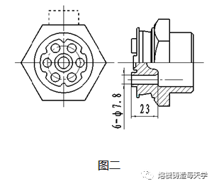
2.2 Example joint B
The structure of joint B is shown in Fig. 2, the dotted line is the gate, on which six long holes of Φ7.8×23 are evenly distributed. The process design adopts a one-line horizontal mold head group tree, four and a half layers of normal shell casting, and “shell local quenching” process, i.e., before casting the shell, the lower part of the shell is quenched into the water for 2~3 seconds to form a temperature gradient and solidification sequence from top to bottom. However, the two holes in the lower part of the gate showed a large proportion of shrinkage phenomenon, and the serious ones had been shrunk through. Analysis: these two holes are located in the lower part of the gate, when pouring, steel flows into the cavity through here, there is a tendency of overheating, and Φ7.8mm holes have been filled with slurry and sand after four and a half layers of normal shell making, which deteriorates the heat dissipation and cooling conditions here, and aggravates the tendency of shrinkage. After making three layers of shells, the method of inserting wooden strips was adopted to eliminate the shrinkage defects in the holes.
2.3 Process Points:
①Insertion of wooden strips can be carried out after three or four layers of shells according to the size of the holes, at this time, it should be ensured that the shells have a certain degree of strength to resist the impact of molten steel.
② The diameter of the inserted wooden strip should be close to the hole of the remaining type shell, so that it is easy to operate and ensure that it can be inserted.
③Insertion of wooden strips should be carried out after 2~3 hours of shell making. Too early, the shell strength is low, easy to damage; too late, the shell has a certain strength, uneven sanding plane, hindering the insertion of wooden strips.
④ Wooden strips are long enough to ensure penetration.
⑤ For ease of operation, the center of the six holes of the wax mold and the angle between the center and the head of the mold are greater than 60° when the tree is formed.
3. Shell local insulation method
3.1 Shell local insulation method: before roasting, in the shell of the local paste insulation materials, delay the cooling, solidification time, open the steel fill shrinkage channel, in order to eliminate shrinkage holes, shrinkage defects of the purpose of loosening.
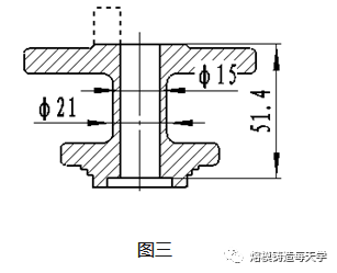
3.2 Example DN15 flange bonnet, flange bonnet structure see figure 3, dotted line for the gate. The structural characteristics of the piece: the upper and lower two thicker flange has a longer flow between the mouth, hole diameter Φ15mm, length 51.4mm, wall thickness of 3mm. casting process design: the upper flange a gate, a word cross mold head group tree, four and a half shells, pouring the lower flange at the use of “shell local quenching” process, the pouring temperature of 1600 ~ 1610 ℃. The casting temperature was 1600~1610℃. However, after pouring, some castings produced shrinkage phenomenon in the middle of the flow hole.
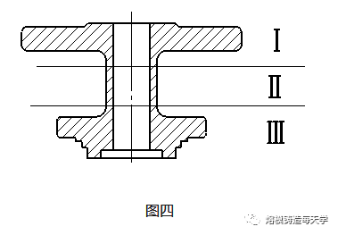
Analysis: the flow hole is long and thin-walled, casting solidification after pouring shrinkage state is shown in Figure 4. the lower flange and the nearby Ⅲ area, due to the shell quenching water cooling effect, the first solidification and get a dense organization; close to the gate Ⅰ area, the contraction of the steel from the gate of the hot steel supplement, also get a dense organization; in the middle of Ⅱ area, the upper part of the steel complementary and the lower part of the cooling effect can't reach there, and the shell is completed, basically has been filled with slurry and sand, heat dissipation and cooling conditions are very poor, so the middle of the flow hole produced shrinkage defects. After the completion of shell making, the flow hole is basically filled with slurry and sand, and the heat dissipation and cooling conditions are very poor, so in the middle of the flow hole produced shrinkage defects. After applying heat preservation material at the outer shell of the flow hole, the solidification time of zone Ⅰ was delayed, and the top-down shrinkage channel was opened, so that the hot steel from the gate was supplemented to zone Ⅱ through zone Ⅰ, which solved the problem of shrinkage in the hole.
4. Ceramic core method:
4.1 Ceramic core method: that is, prefabricated with a certain room temperature and high-temperature strength, coefficient of linear expansion is small, high temperature has the chemical stability of the core placed in the pressure mold pressed wax molds, and then the normal system shell to make the shell with the core of the shell, and then after pouring to remove the core, so as to get the complex cavity castings of the method.
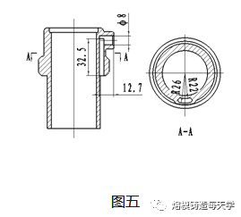
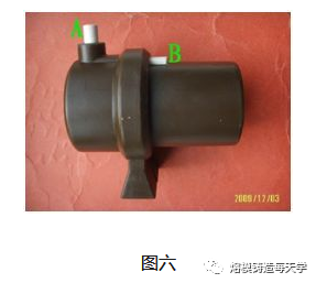
4.2 Example connector: The structure of the connector is shown in Fig. 5. It has a waist-circular narrow groove of about 4 x 12.5 x 32.5 and intersects with a Φ8 hole, forming a vertical runner inside the casting. The runner is so narrow and long that normal shell making is no longer possible, so the ceramic core method is used. The ceramic core was purchased externally, and the pressed wax mold is shown in Fig. 6.
In order to ensure the accurate positioning of the ceramic core, two cores with a length of 10mm are designed, i.e., the cores extend out of the wax mold and do not contact with the metal, see parts A and B in Fig. 6. In order to prevent the ceramic core and shell materials with different coefficients of thermal expansion, resulting in the shell baking or pouring process, the two due to the length of the change is not the same, caused by the core deformation or even fracture, repair wax mold will be one of the core head end coated with a thin layer of repair wax, so that in the shell dewaxing, shell and core head between a certain gap, to prevent damage to the core by force. Normal shell making four and a half layers, pouring temperature 1600~1610℃. Core removal is done by alkali boiling or alkali popping.
4.3 Process points:
① Leave a gap of 0.2~0.8 between the core head and the mold to facilitate the placement of the core.
② When the core is long or the lower core is obstructed, use fine sandpaper to polish the core head or the obstructed part to ensure that the core is smoothly placed in the mold. When the core is short or positioning is not very firm, can be coated with repair wax at the end of the core head to increase the bond between the core and the mold.
③When the core is large, the cleaning of the wax mold after the tree grouping is changed to before the tree grouping. Wipe the wax mold with a soft cloth moistened with cleaning solution to prevent the core head from absorbing moisture and affecting the drying of the shell when the tree is cleaned.
④ Removal of ceramic cores with individual residues can be assisted by mechanical methods or hand blasting.
5.1 Self-hardening core method:
After making 2~3 layers of shells, before the mouth of the narrow groove is filled with paint and sand, pour the patented core-making material J×R-2 slurry prepared with water-soluble phosphate as binder. After filling the slurry, it self-hardens and forms water-soluble phosphate crystals, and then the core is removed to obtain a narrow slot by normal shell making and pouring.
5.2 Example of valve body plug:
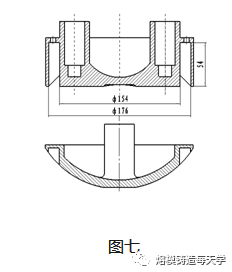
The structure of the valve body plug is shown in Fig. 7. There is a narrow groove of Φ165×11 on the upper surface of the curved surface, and the depth of the groove is 54mm, and whether the groove can be cast out smoothly is the key to this piece. In the process of trial production, has been used in the normal shell five and a half layers, three layers of shell filled with 30-60 mesh mullite sand method, but due to serious fire failure in the groove, the use of “self-hardening core method”, the narrow groove casting smoothly.
①Slurry preparation process
a. Slurry preparation ratio: 100g core material +25ml silica sol, powder-liquid ratio 1:4
b. Slurry mixing time: manual mixing 10~20 minutes
② Shell making process:
The first and second layers of shells are made of zirconium material, and the third layer is made of mullite sand powder. At this time 11mm wide narrow groove about 5~6mm narrow slit, three layers of drying, filling has been blended J×R-2 slurry, 10 minutes later, the slurry self-hardening molding, 1 hour after the slurry strength has been higher, and then make four layers of shells, and normal dewaxing. Shell baking 30 minutes after pouring, the formation of air holes in the casting surface, extend the baking time to more than 60 minutes, air holes are basically eliminated. J×R-2 self-hardening core after pouring, light green, good routing, normal sandblasting basic removal, edge residual part, can be cleaned up manually.
5.3 Key points of the process:
①Information: paste ratio 100g core material plus silica sol 19 ~ 24ml, powder-liquid ratio of about 4.2 ~ 5.2. With the lowering of the powder-liquid ratio, the slurry fluidity becomes better, but the curing time is longer. According to the structure of the piece, taking into account the two factors, we choose the powder-liquid ratio of 4.
② After the slurry is prepared, it should be filled as soon as possible. When the time is long, the fluidity will drop sharply due to curing, affecting the operation.
③ Before filling the slurry, blow the floating sand in the groove to reduce the resistance of slurry flow, and at the same time help to improve the density and strength of the self-hardening core.
④It is advisable to tilt the shell to avoid the involvement of gas.
⑤ This piece of narrow groove depth varies, the use of two grouting, as far as possible to make the groove full of grout, in order to reduce the difficulty of shell making, to avoid running defects.
(6) Strictly control the curing time after grouting. Because the curing process is accompanied by volume expansion, long time will crack the shell, resulting in shell scrap.
6.Discussion and analysis
6.1 There is information that, for carbon steel material, mold casting external dimensions of 10 ~ 50, can be cast wall thickness is generally 2.0 ~ 2.5, the minimum 1.5, stainless steel material due to the high content of Cr, the liquid steel is easy to oxidize, the mobility deteriorates, but appropriate to increase the pouring temperature, increase the superheat of the steel, extend the liquid metal flow time, can be cast wall thickness of 0.7 ~ 1mm castings.
6.2 The elongated holes Φ4×25 on the joint A are intersected at 135°, in general, the ceramic core should be used, after adopting the “soaking slurry method”, under the premise of guaranteeing the quality of the castings, it reduces the cost of using the ceramic core and avoids the difficulty of clearing the shells, which is a kind of economic and practical process method.
6.3 For castings with hole diameter about Φ6~Φ15 Long holes, normal shell making can be realized, but the paint and molding sand fill up all the space of the long holes, which become airtight dead holes, forming new hot joints with hot joint effect and easy to form open shrinkage defects. Inserting wooden strips into the long holes, when the shell is baked, the wooden strips are burned off leaving space, eliminating the hot joints and improving the cooling and heat dissipation conditions after steel pouring. “Shell local insulation method” slows down the cooling time of molten steel, opening up the channel of molten steel to make up for the shrinkage, and at the same time, using “shell local quenching” process, the formation of a top-down sequential solidification conditions, which can eliminate the shrinkage defects of the shrinkage of the long hole.
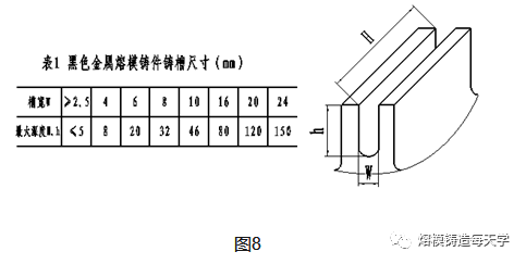
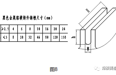
6.4 valve body plug head narrow groove length and width ratio of 47, depth and width ratio of about 5, has exceeded the ferrous metal mold castings listed in Table 1 casting groove size. If a ceramic core is applied, the following three problems exist:
①The core is Φ165×11 circular, the upper surface is curved, the size is big, the weight is heavy and the cost is high.
② The core size is easy to deform, subject to structural and technological constraints are not good positioning, so that the slot size is difficult to meet the requirements of the casting plan.
③ ceramic core removal generally use chemical methods: hydrofluoric acid corrosion method, alkali cooking or alkali explosion, pollution of the environment, there is a certain danger. The use of self-hardening core, to overcome the above problems, the production of castings with accurate dimensions, easy to clear the shell, low cost.
7.Conclusion
Long hole and narrow slot castings are one of the common structures of investment casting, and the production is often caused by defects such as runout, shrinkage and other defects in the holes and slots, resulting in rework and even scrap. This paper describes several process methods, to some extent, can solve these problems and produce castings that meet the requirements.