Shrinkage Porosity in Two Locations – Any Good Solutions Without Altering the Part Geometry
Blog post description.
heweifeng
11/5/20252 min read
Shrinkage Porosity in Two Locations – Any Good Solutions Without Altering the Part Geometry?
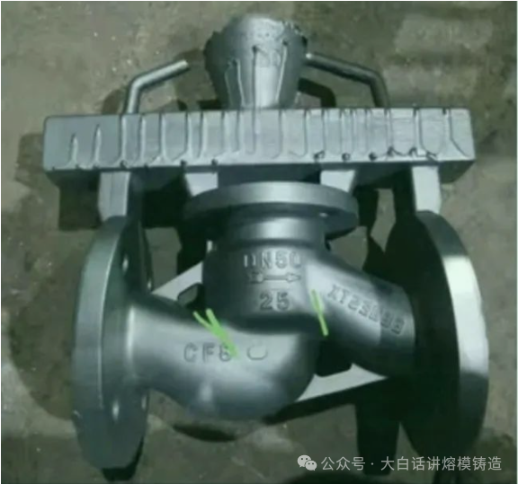
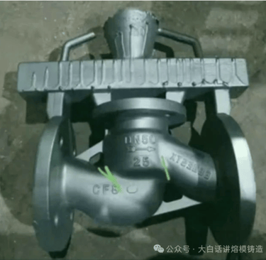
This question was raised by a colleague in an investment casting discussion group. The product is a triple-valve body, cast using a top-gating system with ingates set on its three flanges. After casting, shrinkage porosity was found at two internal corners in the central area, as shown in Figure 1.
We know that shrinkage porosity in a specific area generally indicates two issues: poor heat dissipation and inadequate feeding. Based on the provided images, the shrinkage occurs directly below the central ingates. Intuitively, these locations should be well-fed, being right under two top ingates—so why did shrinkage happen? Let’s break down the issue.
First, let’s examine the gating system. This design uses top-gating, with two central ingates and one on each side. Typically, molten metal would first enter through the two central ingates, hit the bottom, then flow toward the side flanges from the locations where shrinkage appeared. From a filling perspective, metal enters from the center, fills toward the sides, with vents at the top ensuring smooth air escape.
However, one problem stands out: the metal entering from the two central ingates directly impacts the bottom of the cavity before completing filling. This likely results in prolonged metal flow through those areas. Additionally, after shell building, the valve’s internal passages become narrower. These are internal spaces, so heat dissipation is naturally poor. Moreover, the defective areas are junctions of multiple walls—inherently hot spots—with internal corners where the ceramic shell tends to be thicker, further hindering cooling.
All these factors combine to create a pronounced physical hot spot. Assuming the valve wall thickness is uniform (excluding the flanges), even with two ingates above, effective feeding may still be compromised due to the lack of a feeding path. Thus, shrinkage becomes almost inevitable.
In essence, this is an issue of localized overheating. Continuous metal flow through specific areas raises their temperature relative to other sections. When combined with other unfavorable conditions, shrinkage defects are bound to occur.
Some suggest that if the material is 304Ti, shrinkage may occur, while 304 should not—claiming the same gating setup didn’t cause shrinkage in 304. This view seems incomplete. The main difference between 304 and 304Ti is the titanium content. While 304Ti might be more prone to gas porosity or inclusions, I find it hard to believe it specifically causes shrinkage. Moreover, if 304 indeed shows no shrinkage here, it may indicate that the defect is not severe macro-shrinkage, but rather micro-shrinkage or porosity, likely intensified by localized overheating.
Since the root cause appears to be overheating, the solution lies in preventing excessive heat in the affected areas. This can be approached in two ways: either avoid continuous metal flow through those spots, or actively cool them down.
To avoid concentrated metal flow, multi-gating can help distribute the stream more evenly. In this case, that means preventing metal from predominantly entering through the two central ingates. This could involve redesigning the gating system or adjusting shell orientation during pouring to balance the flow—a feasible first solution.
The second approach is cooling the shrinkage-prone zones. This can be done by spot cooling (e.g., localized water quenching) or selectively insulating other areas to create a favorable temperature gradient—the goal is to prevent localized overheating.
These are my thoughts on the issue. Thank you!